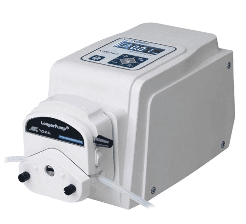
If you are looking for a precision peristaltic pump designed for precise laboratory applications from less than 1 µL/min and up to 366.7 mL/min, depending on the number of rollers in the pump head, you might want to check out the Longer L100-1S-2. This pump delivers your fluids with the highest precision on a wide range of flow rates, and is also relatively cheap.
It can be controlled remotely from your computer which can give you more flexibility and convenience, especially if you want to run complex pumping programs with loops, pauses, and varying flow rates.
In this blog post, we will show you how to communicate with the L100-1S-2 using the LONGER RS485 protocol, which is a serial communication protocol that allows you to send commands and receive responses from the pump. We will also provide some examples and code snippets on how to use Matlab to write and send control command strings to the pump.
TABLE OF CONTENTS
What Do You Need to Communicate with the L100-1S-2 ?
To communicate with the L100-1S-2 using the LONGER RS485 protocol, you will need the following:
- A L100-1S-2 pump with a pump head and a tubing of your choice
- A RS485 control module that plugs into the DB15 port on the rear of the pump
- A serial cable that connects the RS485 control module to your computer or device
- A programming platform (Matlab in the case herein)
- A basic understanding of the data format, command format, and pdu format of the LONGER RS485 protocol (explained below 👇)

How to Set Up the Communication Port ?
Before you can start sending and receiving data from the pump, you need to set up the communication port correctly. Here are the steps to follow:
- Connect the DB15 connector to the DB15 port on the rear of the pump
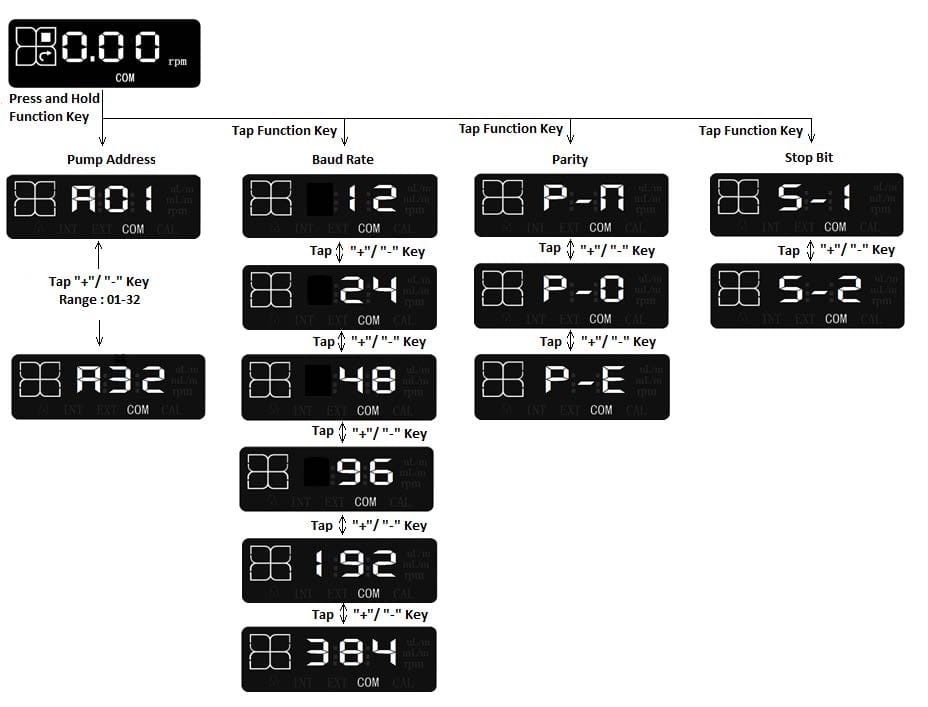
- Turn on the pump and use the keypad on the pump front to enter the remote control setting interface and set the remote control mode to "COM" 🕹️
- Make sure the communication parameters on your programming platform match the ones of the L100-1S-2 (as can be seen in the figure below), which are:
- 1 start bit
- 8 data bits
- Parity: P-n (no parity), P-O (odd parity) or P-E (even parity)
- Stop bit: S-1 (1 stop bit) or S-2 (2 stop bits)
- Baud rate: 12 (1200 bits/s), 24 (2400 bits/s), 48 (4800 bits/s), 96 (9600 bits/s), 192 (19200 bits/s) or 384 (38400 bits/s)
How to Write Control Command Strings to the L100-1S-2 ?
Once you have set up the communication port, you can start writing and sending control command strings to the pump. A control command string is a sequence of hexadecimal characters that follows a specific format, which consists of:
- a start flag (E9H)
- a pump address (1 to 30)
- a length of the pdu (protocol data unit)
- a pdu, which contains the command characters and the parameters for the desired application
- a frame check sequence (fcs), which is obtained by calculating the XOR of the pump address, the length of the pdu, and the pdu itself (compute your fcs using our online frame check sequence XOR calculator)
The pdu and its length depend on the application requested from the pump. Some of the common applications are:
- Set running parameter (rotation speed)
- Read running parameter (rotation speed)
- Set running parameter (flow rate)
- Read running parameter (flow rate)
- Set the pump’s communication parameters
For each application, there is a corresponding set of command characters and parameters that you need to include in the pdu. These parameters are detailed below.
Set Running Parameter (Rotation Speed)
This application consists of writing to the pump. The overall length of the pdu is 6 bytes where the control command string consists of (in the exact same order):
| WJ | Set Speed | State 1 | State 2 |
| 2 bytes | 2 bytes | 1 byte | 1 byte |
- WJ, control command string of 2 bytes, 57 4A
- Set speed (2 bytes) with a speed unit of 0.01 rpm and a maximum speed of 100 rpm
- State 1 (1 byte):
- bit 0 – start/stop bit where 1 is to start the pump and 0 is to stop it
- bit 1 – prime bit where 1 is to prime the pump at full speed (100 rpm) and 0 is to run the pump at a normal speed
- State 2 (1 byte):
- bit 0 – sets the rotation direction where 0 is for clockwise and 1 is for counter-clockwise
The pump will respond with WJ and will display on its front screen the rotation speed and the direction of rotation after receiving the control command string.
Read Running Parameter (Rotation Speed)
This application consists of reading from the pump. The overall length of the pdu is 2 bytes where the control command string is RJ.
The pump’s response consists of:
| RJ | Show Speed | State 1 | State 2 |
| 2 bytes | 2 bytes | 1 byte | 1 byte |
- RJ, control command string of 2 bytes, 52 4A
Set Running Parameter (Flow Rate)
This application consists of writing to the pump. The overall length of the pdu is 8 bytes where the control command string consists of:
| WL | Set flow rate | State 1 | State 2 |
| 2 bytes | 4 bytes | 1 byte | 1 byte |
- WL, control command string of 2 bytes, 57 4C
- Set flow rate (4 bytes) with a nL/min flow rate unit
The pump will respond with WL Show flow rate (4 bytes) and will display on its front screen the flow rate and the direction of rotation after receiving the control command string.
Read Running Parameter (Flow Rate)
This application consists of reading from the pump. The overall length of the pdu is 2 bytes where the control command string is RL.
The pump’s response consists of:
| RL | Show flow rate | State 1 | State 2 |
| 2 bytes | 4 bytes | 1 byte | 1 byte |
- RL, control command string of 2 bytes, 52 4C
Set the Pump's Communication Parameters
This application consists of writing to the pump in order to set the different communication parameters. The overall length of the pdu is 8 bytes where the control command string consists of:
| WID | Address | Baud rate | Parity | Stop bit |
| 3 bytes | 1 byte | 2 bytes | 1 byte | 1 byte |
- WID, control command string of 3 bytes, 57 49 44
- Pump address (1 byte), valid range: 1-30
- Baud rate (2 bytes), high byte is 00H and low byte is as presented in the table below:
| Low byte | Baud rate (bits/s) |
|---|---|
| 01H | 1200 |
| 02H | 2400 |
| 03H | 4800 |
| 04H | 9600 |
| 05H | 19200 |
| 06H | 38400 |
| Other value | Invalid |
- Parity (1 byte), setting as in the table below:
| Setting | Parity |
|---|---|
| 01H | No Parity |
| 02H | Odd Parity |
| 03H | Even Parity |
| Other value | Invalid |
- Stop bit (1 byte), setting as in the table below:
| Setting | Stop bit |
|---|---|
| 01H | 1 stop bit |
| 02H | 2 stop bits |
| Other value | Invalid |
Examples of Control Command Strings
- Set the L100-1S-2 to run counter-clockwise at a rotating speed of 20 rpm
Control command string: E9 01 06 57 4A 07 D0 01 01 CD
- E9 as the flag
- 01 as the address 1 of the pump
- 06 as the length of the pdu (57 4A 07 D0 01 01)
- 57 4A as command characters WJ
- 07 D0 refers to the rotation speed, 07 D0(hex) = 2000(dec); the speed unit being 0.01 rpm ⇒ the rotation speed = 20 rpm (check our online base conversion tool)
- 01 to start the pump at normal speed
- 01 to run the pump counter-clockwise
- CD as the XOR result of 01 (pump address), 06 (pdu length) and 57 4A 07 D0 01 01 (pdu)
- Set the L100-1S-2 to run clockwise at a flow rate of 3 mL/min
Control command string: E9 01 08 57 4C 00 2D C6 C0 01 00 38
- E9 as the flag
- 01 as the address 1 of the pump
- 08 as the length of the pdu (57 4C 00 2D C6 C0 01 00)
- 57 4C as command characters WL
- 00 2D C6 C0 refers to the flow rate, 00 2D C6 C0(hex) = 3000000(dec); the flow rate unit being nL/min ⇒ the flow rate = 3000000 nL/min = 3 mL/min
- 01 to start the pump at normal speed
- 00 to run the pump clockwise
- 38 as the XOR result of 01 (pump address), 08 (pdu length) and 57 4C 00 2D C6 C0 01 00 (pdu)
🚨Do not hesitate to use our user-friendly online command string generator to effortlessly generate precise control command strings for your L100-1S-2.
How to Communicate with the L100-1S-2 Using Matlab ?
Matlab code snippets showing how to open the serial port, write and send control command strings to the pump and write a simple pumping program are presented below.
From the first example just presented above, the following Matlab code snippet makes the L100-1S-2 run counter-clockwise at a rotational speed of 20 rpm.
					%%% RUN PUMP 1, COUNTER-CLOCKWISE, AT A ROTATING SPEED OF 20 RPM

% Open the serial port with the data format corresponding to the L100-1S-2
% The parameters in the command need to be the same as the communication
parameters set for the pump
s = serialport('COM3', 9600, 'Parity', 'None', 'DataBits', 8, 'StopBits', 1);

% Write the corresponding control command string
Str = 'E9 01 06 57 4A 07 D0 01 01 CD';

% Read data from Str, convert it according to the format specified '%2x' (hexadecimal conversion), transpose and return the results in an array
Data = sscanf(Str, '%2x').';

% Write the Data to the pump in the form of an unsigned integer 8bits
write(s, Data, uint8);
- In a second code snippet, let’s make the pump run counter-clockwise at a flow rate of 5 mL/min for 10s, then make it run clockwise at a flow rate of 3 mL/min for 30s before stopping it.
					%%% RUN PUMP 1 COUNTER-CLOCKWISE AT A FLOW RATE OF 5 mL/min FOR 10s, THEN CLOCKWISE AT A FLOW RATE OF 3 mL/min FOR 30s BEFORE STOPPING IT

% Open the serial port with the data format corresponding to the L100-1S-2
% The parameters in the command need to be the same as the communication
parameters set for the pump
s = serialport('COM3', 9600, 'Parity', 'None', 'DataBits', 8, 'StopBits', 1);

% Run pump 1 counter-clockwise at a flow rate of 5 mL/min for 10s
Str = 'E9 01 08 57 4C 00 4C 4B 40 01 01 55'; % corresponding control command string
Data = sscanf(Str, '%2x').';
write(s, Data, uint8); % write the Data to the pump

% 10s delay with a visible timer
Pumping_time = 10;
for Pumping_time = 10:-1:1
    pause(1)
    disp(['Remaining_time: ' num2str(Pumping_time)])
end

% Run pump 1 clockwise at a flow rate of 3 mL/min for 30s
Str = 'E9 01 08 57 4C 00 2D C6 C0 01 00 38'; % corresponding control command string
Data = sscanf(Str, '%2x').';
write(s, Data, uint8); % write the Data to the pump

% 30s delay with a visible timer
Pumping_time = 30;
for Pumping_time = 30:-1:1
    pause(1)
    disp(['Remaining_time: ' num2str(Pumping_time)])
end

% Stop the pump
Str = 'E9 01 08 57 4C 00 2D C6 C0 00 00 39'; % corresponding control command string; we took the previous command string and changed the State 1 byte from 01 (start the pump) to 00 (stop the pump) and of course computed the new fcs
Data = sscanf(Str, '%2x').';
write(s, Data, uint8); % write the Data to the pump
Conclusion
We hope this blog post has helped you understand how to control the Longer L100-1S-2 peristaltic pump remotely via Matlab using the LONGER RS485 protocol. You can also use other programming platforms such as Python to write and send control command strings to the pump and read and interpret the responses from the pump. For more details about this topic, check our blog post “How to Control the Longer L100-1S-2 Pump via Python ?”.
If you have any questions or feedback, please feel free to contact us at contact@darwin-microfluidics.com.


How to Control the Longer L100-1S-2 Pump via Python ? - Darwin Microfluidics
[…] We hope this blog post has helped you understand how to control the Longer L100-1S-2 peristaltic pump remotely via Python using the LONGER RS485 protocol. You can also use other programming platforms such as Matlab to write and send control command strings to the pump and read and interpret the responses from the pump. For more details about this topic, check our blog post “How to Control the Longer L100-1S-2 Pump via Matlab ?”. […]
How to Remotely Control your Longer Peristaltic Pumps ?
[…] How to Control the Longer L100-1S-2 Pump via Matlab ? […]