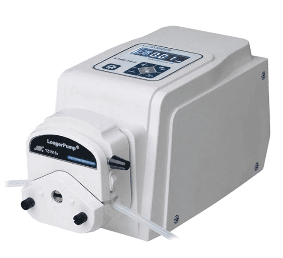
Peristaltic pumps play a crucial role in microfluidic research and medical diagnostics, offering precise fluid control with minimal risk of contamination. Among the many available options, Longer pumps, manufactured by Longer Precision Pump Co., Ltd., have gained a reputation for their reliability, precision, and versatility.
One of the standout features of Longer peristaltic pumps is their ability to be controlled remotely from a computer, which allows users to run complex pumping programs involving loops, pauses, and varying flow rates with greater flexibility and convenience.
In this blog post, we will dive into controlling Longer peristaltic pumps using the Modbus RTU protocol, a widely used serial communication protocol that enables sending commands and receiving responses from the pump. While the specifics of the Modbus protocol can vary slightly between different pump models, for this article, we’ll be using the Longer L100-1S-2 peristaltic pump as a reference example. We’ll also walk you through Python examples and code snippets, which you can directly copy and use in your own scripts to easily control your pump.
🚨 You can apply the same concepts and code examples to other Longer pumps, making adjustments to some commands based on the specific protocol of your pump model.
What Do You Need to Communicate with your Longer Pump?
To communicate with a Longer peristaltic pump using the Modbus RTU protocol, you will need the following:
- A Longer pump with a pump head and tubing of your choice
- A RS485 control module that plugs into the DB15 port on the rear of the pump
- A serial cable that connects the RS485 control module to your computer or device
- A programming platform (Python in the case herein)
- A basic understanding of the Modbus RTU protocol (explained below 👇).
How to Set Up the Communication Port?
Before you can start sending and receiving data from the pump, you need to set up the communication port correctly. Here are the steps to follow:
- Connect the DB15 connector to the DB15 port on the rear of the pump
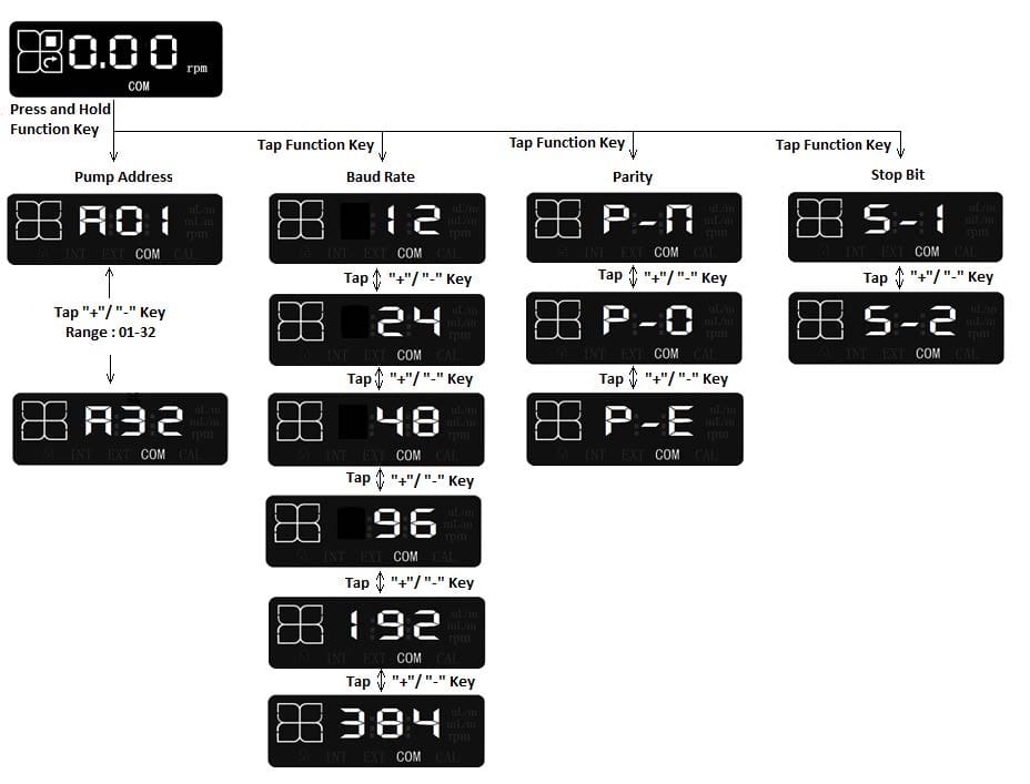
- Turn on the pump and use the keypad on the pump front to enter the remote control setting interface and set the remote control mode to "COM" 🕹️
- Make sure the communication parameters on your programming platform match those of the L100-1S-2 (as can be seen in the figure below), which are:
- 1 start bit
- 8 data bits
- Parity: P-n (no parity), P-O (odd parity) or P-E (even parity)
- Stop bit: S-1 (1 stop bit) or S-2 (2 stop bits)
- Baud rate: 12 (1200 bits/s), 24 (2400 bits/s), 48 (4800 bits/s), 96 (9600 bits/s), 192 (19200 bits/s) or 384 (38400 bits/s).
🚨 The communication is valid only when the pump displays the running screen of the communication control mode "COM".

Understanding the Modbus RTU Protocol
The Modbus RTU protocol is a widely adopted communication standard used in industrial and automation systems to exchange data between devices. Known for its simplicity and robustness, it is ideal for controlling equipment like Longer peristaltic pumps. In this section, we will delve into the key elements of Modbus RTU, including its communication format, Cyclic Redundancy Check (CRC), and communication settings. We’ll also explore the structure of Modbus RTU messages and the command set used to control Longer pumps effectively.
Modbus RTU Standard Communication Format
The Modbus protocol is a commonly used communication framework that facilitates master-slave interactions between intelligent devices. A Modbus message transmitted from a master to a slave includes the slave’s address, a specific command (such as reading or writing to a register), the accompanying data, and a checksum for error checking.
This message format is described in the table below.
| Field | Size | Description |
|---|---|---|
| Slave Address | 1 Byte | Address of the pump. The range is 1-32; 0 is used for broadcast communication. |
| Function Code | 1 Byte | Instruction for the slave device: - 03H: Read holding registers - 06H: Write single register - 10H: Write multiple registers |
| Data area | 0 – 252 Bytes | Data to be transmitted (variable length) |
| CRC Check | 2 Bytes | Cyclic Redundancy Check for error detection: - CRC low (1 Byte): Lower byte of the CRC - CRC high (1 Byte): Higher byte of the CRC |
CRC Check with CRC-16 in Python
CRC (Cyclic Redundancy Check) is a vital technique for detecting errors in data transmission. In the following, we’ll demonstrate how to implement CRC-16, the one used in the American binary synchronous system, using Python. In CRC-16, the error-detection algorithm employs a polynomial G(X) = X16 + X15 + X2 + 1 to generate the checksum. This polynomial defines the mathematical operations performed on the bits of the message during the CRC calculation process. An overview of the algorithm is detailed below:
- Initialize a 16-bit register with the hexadecimal value FFFF (all ones), referred to as the CRC register.
- XOR the first 8 bytes of the message with the low byte of the CRC register. Store the result back in the CRC register.
- Shift the CRC register one bit to the right, with the most significant bit (MSB) set to zero.
- Check the least significant bit (LSB) of the CRC register:
- If LSB is 0, repeat step 3 (shift operation).
- If LSB is 1, XOR the CRC register with the polynomial value 0xA001 (1010 0000 0000 0001).
- Repeat steps 3-4, for a total of 8 shifts, to process each byte.
- Repeat steps 2-5 for each byte in the message until all bytes have been processed.
- The final content of the CRC register is the CRC value.
Communication Settings
Each byte of data has a structure consisting of 1 start bit, 8 data bits, 1 parity bit, and 1 or 2 stop bit(s). Bits are sent in order from the least significant bit (LSB) to the most significant bit (MSB).
For integers (2 bytes), the data is arranged with the second byte first followed by the first byte. For example, the hexadecimal value 2378H is sent as 23H 78H. For long integers and floats (4 bytes), the data is arranged with the fourth byte first, followed by the third, second, and first bytes.
Modbus RTU Message Frame Format
The Modbus RTU message frame rate is the one described in the table below.
| Field | Size | Description |
|---|---|---|
| Start | ≥ 3.5 characters | Indicates the start of transmission. |
| Address | 8 Bits | Address of the slave device. |
| Function Code | 8 Bits | Instruction for the slave device. |
| Data | N x 8 Bits | Data to be transmitted (variable length, N bytes). |
| CRC Check Code | 16 Bits | Cyclic Redundancy Check for error detection. |
| End | ≥ 3.5 characters | Indicates the end of transmission. |
🚨 Ensure that the message frame is transmitted continuously without idle spaces between characters greater than 1.5 character times. Incomplete message frames, indicated by excessive idle space, should be discarded by the receiving node.
Parameter Setting
The table below outlines the essential parameter settings for the L100-1S-2 model. These parameters may vary between different Longer pump models, either due to the specific functions available or the unique address and descriptions associated with each parameter.
| Parameter | Address | Data Type | Description |
|---|---|---|---|
| Speed | 0x01 | uint_16 | Range: 1-10,000, corresponding to 0.01 rpm to 100 rpm, in increments of 0.01 rpm. Pump displays speed in rpm. Example: 100 = 0.01 rpm, 10000 = 100 rpm. |
| Flow Rate | 0x02 | uint_16 | The high bytes of the flow rate. Used with the low byte of flow rate. The unit of flow rate is 1 nL/min. Example: 02 FA F0 80H = 50.0 mL/min. |
| 0x03 | uint_16 | The low bytes of the flow rate. Used with the high byte of flow rate. The unit of flow rate is 1 nL/min. Example: 02 FA F0 80H = 50.0 mL/min. | |
| Pump State | 0x04 | uint_16 | Low byte is valid. BIT0: Run/Stop (0 = stop, 1 = run). BIT1: Full speed (0 = normal speed, 1 = full speed). BIT2: Speed/flow rate display. BIT3: Reserved. BIT4: Direction (0 = CW, 1 = CCW) |
| Pump Address | 0x05 | uint_16 | Low byte is valid. Valid range: 1-32 |
| Baud Rate | 0x06 | uint_16 | Low byte is valid. 01H: 1200 bps 02H: 2400 bps 03H: 4800 bps 04H: 9600 bps 05H: 19200 bps 06H: 38400 bps |
| Parity | 0x07 | uint_16 | Low byte is valid. 01H: No parity 02H: Odd parity 03H: Even parity |
| Stop Bit | 0x08 | uint_16 | Low byte is valid. 01H: 1 stop bit 02H: 2 stop bits |
| Keypad Lock | 0x09 | uint_16 | Low byte: Enables keypad lock function. 01H: Disabled 02H: Enabled High byte: Delay before locking. 00H: 30s 01H: 60s 02H: 180s 03H: 300s 04H: 480s 05H: 600s |
💡 Important Notes:
- The Longer Modbus RTU protocol supports only function codes 03H (read registers), 06H (write single register), and 10H (write multiple registers).
- When using function code 06H, the pump operates based on the last command received, showing the speed with a speed parameter and the flow rate with a flow rate parameter.
- To set the flow rate, both the high byte and low byte must be specified simultaneously. The unit for flow rate is 1 nL/min (e.g., the command 02 FA F0 80H corresponds to 50.0 mL/min).
- If the flow rate or speed exceeds the allowable range, the pump displays the maximum or minimum value without issuing a warning.
Conversion Relationship Between Flow Rate and Speed
The relationship between flow rate and speed for the L100-1S-2 can be described by the equation: Q = V x f
Where Q represents the flow rate in mL/min, V denotes the speed in rpm, and f is the flow rate coefficient measured in mL/r, which defaults to 1.
The default value f = 1 indicates a direct correlation between speed and flow rate under standard conditions. This simplicity makes it straightforward for operators to optimize the pump settings for their specific applications.
How to communicate with the L100-1S-2 using Python?
A basic Python library designed to facilitate communication and control of Longer peristaltic pumps using the Modbus RTU protocol is presented in this section. It encapsulates essential functionalities, such as setting the pump speed, flow rate, and direction, as well as starting and stopping the pump with ease.
This library is specifically written based on the protocol of the Longer L100-1S-2 peristaltic pump and serves as an example that can be modified. By adjusting the commands and parameters as needed, users can adapt it to fit the Modbus RTU protocol of their specific Longer pump model.
🚨🚨🚨 Important Note
- When viewing this code, please be aware that <, >, and & symbols might not display correctly due to formatting issues. These should appear as standard Python code syntax, so make sure to interpret < as <, > as >, and & as &.
					'''
-------------------------------------------------------------
Longer Peristaltic Pump Control Library Using Modbus Protocol
-------------------------------------------------------------
'''

import serial
import time

#------------------------------------------------------#
#   LIBRARY MANAGING THE COMMUNICATION WITH THE PUMP   #
#------------------------------------------------------#

class Longer_Pump:

    # Initialize the class with serial communication parameters
    def __init__(self, port, address=1, baudrate=9600, parity=serial.PARITY_NONE, bytesize=8, stopbits=1, timeout=1):
        """
        Parameters:
        port (str): The COM port for serial communication.
        address (int): Modbus address of the pump (default is 1).
        baudrate (int): The baud rate (default is 9600).
        parity (str): Parity for serial communication (default is none).
        bytesize (int): Number of data bits (default is 8).
        stopbits (int): Number of stop bits (default is 1).
        timeout (int): Timeout for serial communication (default is 1s).
        """
        self.ser = serial.Serial(port=port, baudrate=baudrate, parity=parity, bytesize=bytesize, stopbits=stopbits, timeout=timeout)
        self.address = address

    # Open the serial port for communication with the pump
    def connect(self):
        if not self.ser.is_open:
            self.ser.open()

    # Close the serial port to end communication with the pump
    def disconnect(self):
        if self.ser.is_open:
            self.ser.close()

    # Calculate the CRC for Modbus communication
    def _calculate_crc(self, data):
        """
        Parameters:
            data (bytearray): The data for which to calculate the CRC.
        Returns:
            bytes: The calculated CRC as a 2-byte value.
        """
        crc = 0xFFFF
        for byte in data:
            crc ^= byte
            for _ in range(8):
                if crc & 0x0001:
                    crc >>= 1
                    crc ^= 0xA001
                else:
                    crc >>= 1
        return crc.to_bytes(2, byteorder='little')

    # Send a command to the pump using the Modbus protocol
    def _send_command(self, function_code, register_address, data):
        """
        Parameters:
            function_code (int): e.g., 0x03 for read, 0x06 for write.
            register_address (int): to read from or write to.
            data (list or int): to be sent (for writing registers).
        Returns:
            bytes: The response from the pump.
        """

        # Prepare the command payload for Modbus
        payload = bytearray([self.address, function_code])
        payload.extend(register_address.to_bytes(2, byteorder='big'))

        if isinstance(data, list):
            # For multi-register commands (function code 0x10)
            number_of_registers = len(data)
            payload.extend(number_of_registers.to_bytes(2, byteorder='big'))
            payload.append(len(data) * 2)  # Byte count for the data
            for value in data:
                payload.extend(value.to_bytes(2, byteorder='big'))
        else:
            # For single-register commands (function code 0x06)
            payload.extend(data.to_bytes(2, byteorder='big'))

        # Append CRC
        crc = self._calculate_crc(payload)
        payload.extend(crc)

        # Send the command to the pump
        self.ser.write(payload)
        response = self.ser.read(8)  # Adjust this based on expected response length
        return response

    # Set the pump speed in RPM (0.01 RPM increments)
    def set_speed(self, speed_rpm):
        """
        Parameters:
            speed_rpm (float): The desired speed in RPM.
        """
        speed_value = int(speed_rpm * 100)  # 0.01 RPM increments
        response = self._send_command(0x06, 0x01, speed_value)
        print(f"Set speed response: {response.hex()}")

    # Set the pump flow rate in mL/min (combined high/low bytes)
    def set_flow_rate(self, flow_rate_ml_min):
        """
        Parameters:
            flow_rate_ml_min (float): The desired flow rate in mL/min.
        """
        flow_rate_nl_min = int(flow_rate_ml_min * 1_000_000)  # Convert mL/min to nL/min
        high_byte = (flow_rate_nl_min >> 16) & 0xFFFF
        low_byte = flow_rate_nl_min & 0xFFFF
        response = self._send_command(0x10, 0x02, [high_byte, low_byte])
        print(f"Set flow rate response: {response.hex()}")

    # Start the pump and set the display mode to either 'speed' (RPM) or 'flow_rate' (mL/min)
    def start(self, display_mode="speed"):
        """
        Parameters:
            display_mode (str): 'speed' or 'flow_rate'.
        """
        if display_mode == "speed":
            pump_state = 0b00000001  # Run + Display Speed
        elif display_mode == "flow_rate":
            pump_state = 0b00000101  # Run + Display Flow Rate
        else:
            raise ValueError("Invalid display_mode. Use 'speed' or 'flow_rate'.")
        response = self._send_command(0x06, 0x04, pump_state)
        print(f"Start pump response: {response.hex()}")

    # Stop the pump and set the display mode to either 'speed' (RPM) or 'flow_rate' (mL/min)
    def stop(self, display_mode="speed"):
        """
        Parameters:
            display_mode (str): 'speed' or 'flow_rate'.
        """
        if display_mode == "speed":
            pump_state = 0b00000000  # Stop + Display Speed
        elif display_mode == "flow_rate":
            pump_state = 0b00000100  # Stop + Display Flow Rate
        else:
            raise ValueError("Invalid display_mode. Use 'speed' or 'flow_rate'.")
        response = self._send_command(0x06, 0x04, pump_state)
        print(f"Stop pump response: {response.hex()}")

    # Set the pump direction (CW or CCW)
    def set_direction(self, direction):
        """
        Parameters:
            direction (str): 'CW' for clockwise, 'CCW' for counter-clockwise.
        """
        direction_value = 0x0010 if direction.upper() == 'CCW' else 0x0000
        response = self._send_command(0x06, 0x04, direction_value)
        print(f"Set direction response: {response.hex()}")

    # Custom function: Run the pump at the specified speed for a certain amount of time and then stop
    def run(self, speed_rpm, run_time_s, direction='CW'):
        """
        Parameters:
            speed_rpm (float): The speed at which to run the pump in RPM.
            run_time_s (int): The time to run the pump in seconds.
            direction (str): 'CW' or 'CCW'.
        """
        try:
            self.set_speed(speed_rpm)
            self.set_direction(direction)
            self.start(display_mode="speed")
            # Run the pump for the specified time
            for remaining_time in range(run_time_s, 0, -1):
                print(f"Running... {remaining_time} seconds remaining")
                time.sleep(1)
        finally:
            self.stop(display_mode="speed")

#-----------------------------------------------------------------------#
#   EXAMPLES ON HOW TO USE THE DEFINED CLASS TO CONTROL A LONGER PUMP   #
#-----------------------------------------------------------------------#

pump = Longer_Pump(port='COM7', address=1)  # Adjust port and address as needed
pump.connect()

# Run the pump at 40 rpm
pump.set_speed(40.00)  # Speed in RPM
pump.start(display_mode="speed")
pump.stop(display_mode="speed")

# Set direction to counter-clockwise
pump.set_direction('CCW')

# Run the pump in flow rate mode at 35 mL/min
pump.set_flow_rate(35)  # Flow rate in mL/min
pump.start(display_mode="flow_rate")
pump.stop(display_mode="flow_rate")  # Stop the pump

# Run the pump counter-clockwise at 10 RPM for 25 seconds
pump.run(speed_rpm=10.0, run_time_s=25, direction='CCW')

# Disconnect the pump
pump.disconnect()
Conclusion
In this blog post, we’ve covered how to control Longer peristaltic pumps using the Modbus RTU protocol, offering insights into the communication format and providing a Python library to help you get started. Whether you’re working with the L100-1S-2 model or adapting the code to suit a different pump, we hope this guide serves as a valuable resource.
Stay tuned for more tutorials, and practical applications in future posts. Until then, happy pumping and coding! 💻
📧 If you have any questions or feedback, please feel free to contact us at support@darwin-microfluidics.com.


